
Lecture - 05
Gravity Dam

A gravity dam is a massive structure designed to hold back water by utilizing its own weight to resist the horizontal force of the water pressing against it. These dams are typically made of concrete or masonry and are shaped to ensure stability against overturning, sliding, and material failure. Gravity dams are commonly used for water storage, flood control, and hydroelectric power generation.
Forces Acting on a Gravity Dam
·
Weight of the Dam
·
Water Pressure
·
Uplift Pressure
·
Earthquake Forces
·
Silt Pressure
·
Wave Pressure
·
Ice Pressure
Weight of the Dam
· The
self-weight of the dam acts vertically downward through its center of gravity.
· This
force is crucial for providing stability against overturning and sliding.
Water pressure
When U/S face is vertical

When U/s face partly
vertical and partly inclined there will have horizontal component and vertical
component. Vertical component is equal to the weight of water in inclined
portion. If there is tail water on D/S it will have horizontal and vertical
component.

Uplift Pressure
Uplift pressure is a
critical force acting on gravity dams. It occurs due to water seeping under the
dam through the foundation or through cracks in the dam itself. This water
exerts an upward pressure, reducing the effective weight of the dam and potentially
destabilizing it. Uplift pressure is a major consideration in the design and
stability analysis of gravity dams.

Earthquake Forces
·
In seismic regions, earthquake forces can
act horizontally or vertically, causing additional stresses on the dam.
·
These forces depend on the dam's mass, the
intensity of the earthquake, and the dam's dynamic response.
Earthquake forces impact
both the dam structure and the water in the reservoir, causing them to vibrate.
The vibration of the dam generates what is known as the Inertia Force,
while the vibration of the water produces the Hydrodynamic Force.
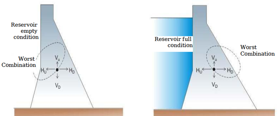
Earthquakes can cause the ground to shake horizontally in two directions and
vertically. For design purposes, engineers must account for the worst-case
scenario, considering the combination of forces that poses the greatest threat
to the dam's stability. This ensures the structure can withstand the most
unfavorable conditions.
Earthquake wave may move
in any direction, and for design purposes it has to be resolved in vertical and
horizontal components. Hence two accelerations induced one is vertical acceleration
and other is horizontal acceleration.
Effect of vertical acceleration (αv):
Inertia force = Mass X acceleration due to earthquake
𝑷𝒆𝒗 =
𝑴 × 𝜶𝒗 =
𝑾 / 𝒈 × 𝜶𝒗
The net effective weight of the dam = W - 𝑾 / 𝒈 × 𝜶𝒗
If, 𝛼𝑣 =
𝑲𝒗 𝐠
[ where, 𝑲𝒗 is
the fraction of gravity adopted for vertical acceleration such as
0.1 or 0.2 etc]
Then the net effective weight of the dam = W - 𝑾 / 𝒈 × 𝑲𝒗 x
𝐠 = W [1- 𝑲𝒗]
Effect of horizontal acceleration (αh):
·
Hydrodynamic pressure of the water
·
Inertia force in body of the dam in the
horizontal direction
Hydrodynamic pressure
Hydrodynamic pressure
refers to the additional pressure exerted on a dam due to the vibration or
movement of the water in the reservoir during an earthquake. When an earthquake
occurs, the water in the reservoir vibrates, creating dynamic forces that act
on the upstream face of the dam. These forces are in addition to the normal
hydrostatic pressure and must be considered in the design of dams, especially
in seismically active regions.

According to Von-Karman
Hydrodynamic force, Pe
= 0.555. kh γw H2 and it acts at the height of 4H/3π
above the base.
where, 𝑲h
is
the fraction of gravity adopted for horizontal acceleration such as
0.1 or 0.2 etc
Moment of this force about base
= Me
= Pe (4H/3π) = 0.424 Pe H
According to Zanger’s Formula
Pe = 0.726 pe H,
where, pe = Cm kh γw H
Pe = 0.726 Cm
kh γw H2
where, Cm = maximum value of pressure
co-efficient for a given constant slope
= 0.735 (θ/90),
where θ is the angle in degrees, which the u/s face of the dam makes with the
horizontal.
The moment of this force about the base
Me = 0.412 Pe H 2
If u/s partly inclined and less then
H/2 it can be taken as vertical. If slope extends more than
H/2 the overall slope may be taken as the value of θ for Cm
calculation.

Horizontal Inertia Force
The horizontal inertia force = (W/g) . αh
= (W/g) . kh . g = W. kh
Silt Pressure
Sediment deposited in the
reservoir exerts additional horizontal pressure on the upstream face of the
dam.
P𝒔𝒊𝒍𝒕 =
𝟏/𝟐 𝜸𝒔 𝒉𝟐 [(𝟏
- 𝒔𝒊𝒏∅)
/ (𝟏
+ 𝒔𝒊𝒏∅)],
it acts at h/3 from base.
𝛾𝑠 =
Submerged unit weight of silt
ℎ
= height of silt deposited
∅ = angle of
internal friction
If u/s face is inclined
the vertical weight of the silt supported on slope act as a vertical force.
According to USBR
P𝒔𝒊𝒍𝒕-horizontal =
1.8 𝒉𝟐
kN/m run
P𝒔𝒊𝒍𝒕-vertical =
4.6 𝒉𝟐
kN/m run
Wave Pressure
Wind-generated waves in
the reservoir can exert additional pressure on the dam, particularly near the
water surface.

Wave height

Where,
hw = height of water from top of crest to bottom
of trough in meters
V = wind velocity in km/hr
F = Fetch or straight length of water expanse in
km.
The maximum pressure intensity due to wave
action may by given by
Pw
= 2.4 γw . hw
and acts at hw/2 meters above the still water surface.
The pressure distribution may be assumed to be
triangular, of height 5hw/3
Hence the total force due to wave
action
Pw = ½ ( 2.4 γw
. hw). 5hw/3 = 19.62 hw2 kN/m
This force acts at a distance 3/8 hw
above the reservoir surface.
Ice Pressure
o In cold
climates, ice formation on the reservoir surface can exert pressure on the dam
as it expands or moves.
o This force
acts linearly along the length of the dam and at the reservoir level.
o The magnitude
of this force varies from 250 to 1500 kN/m2 depending upon the
temperature variations. On average a value of 500 kN/m2 allowed
under ordinary conditions.
Combinations of
forces for design
Two cases
1.
Reservoir full
2.
Reservoir empty
Case 1: Reservoir
full
Major
Forces = weight of the dam + external eater pressure + uplift pressure +
earthquake forces
Minor Forces = silt
pressure + ice pressure + wave pressure
For most
conservative design a situation arises when all the forces may act together.
But According to USBR classified as
·
Normal load combination
·
Extreme load combination
Normal load
combination
a)
Water pressure up to normal pool
level + normal uplift + silt pressure + ice pressure.
This
class of loading taken when ice force is serious.
b)
Water pressure up to normal pool
level + normal uplift + silt pressure + earthquake forces
c)
Water pressure up to maximum reservoir
level + normal uplift + silt pressure
Extreme load
combination
a) Water
pressure up to maximum reservoir level + extreme uplift pressure (without any
reduction due to drainage) + silt pressure
Case 2: Reservoir empty
a) Empty
reservoir without earthquake forces to be computed for determining bending
diagrams for reinforcement design, grouting studies.
b) Empty
reservoir with a horizontal earthquake force produced towards the upstream has
to be checked for non-development of tension at toe.
Modes of Failure
of Gravity Dam
1) By
overturning or rotation about toe
2) By
crushing
3) By
development of tension
4) By
shear failure called sliding