
Lecture-08

Design of Earthen Dam
The initial design of an earthen dam is primarily based on past experiences. Several key parameters should be taken into account during the design process, including:
·
Top Width
·
Freeboard
·
Settlement Allowance
·
Slope
·
Cut-off Trench
·
Downstream Drainage System
Top Width
The minimum top width (W) should be sufficient to enhance practicality and provide protection against wave action and seismic shocks. In some cases, it also serves as a transportation route. The required width depends on the height of the earthen dam and can be determined using the following formula:
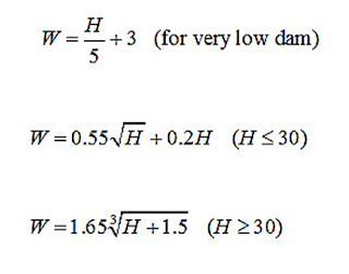
Where H = the height of the dam (m).
Free board
The vertical distance
between the top of the dam and the full supply level of the reservoir, or any
additional height, is known as freeboard. It serves as a safety feature to
protect the dam from high-flow conditions, such as waves and storm runoff exceeding
the design frequency, preventing overtopping of the embankment. The U.S. Bureau
of Reclamation (U.S.B.R.) provides recommended freeboard values for earthen
dams of varying heights, as outlined in the table below.

An additional freeboard
up-to 1.5 m should be provided for dams situated in areas of low temperature
for frost action.
Settlement Allowance
Settlement occurs due to
the compression of fill and foundation materials, leading to a reduction in the
dam's storage capacity. This phenomenon is influenced by the type of fill
material used, as well as the construction method and speed. The settlement
typically ranges from 10% of the design height for manually compacted earth-fill
to 5% for machine-compacted earth-fill.
Slope
The side slopes depend
upon various factors such as the type of nature of the dam and foundation
materials, height of dam, etc. The recommended values of side slopes given by
Terzaghi are tabulated below.

Cutoff Trench
A cutoff trench is
constructed to minimize seepage beneath the foundation and to prevent piping in
the dam. It should be positioned such that its centerline lies within the
impervious core. The trench must have a depth of at least 1 meter. The bottom
width of the cutoff trench (B) is determined through specific calculations.
B = h – d
where h = reservoir head above the
ground surface (m); and
d = depth of cutoff
trench below the ground surface (m).
Downstream Drainage System
The downstream drainage
system is implemented by incorporating filter material within the earthen dam
that is more permeable than the surrounding fill material. This helps to lower
pore water pressure, thereby enhancing the dam's stability.
Three types of drains commonly used for this purpose
are:
o
Toe Drains
o
Horizontal Blanket Drains
o Chimney Drains
Phreatic Line in Earthen Dam
The phreatic line, also
referred to as the seepage line or saturation line, is an imaginary boundary
within a dam section. Below this line, hydrostatic pressure is positive, while
above it, the pressure is negative. At the phreatic line itself, the
hydrostatic pressure equals atmospheric pressure, which is considered zero.
Above the phreatic line lies the capillary zone, or capillary fringe, where
hydrostatic pressure is negative. Below the phreatic line, the movement of
seepage water decreases the soil's effective weight.
Determination of the Phreatic Line:
Before constructing the
flow net for an earth dam section, it is essential to accurately plot the
phreatic line. The following methods are commonly employed:
1. Casagrande’s
Graphical Methods: These
techniques are used to determine the phreatic line, both for cases with and
without a horizontal drainage filter.
2. Analytical
Methods: These approaches
are applied to calculate the phreatic line for embankments featuring an
inclined discharge face but lacking a horizontal filter.
Casagrande’s Graphical Method (with filter)
Casagrande proposed that the phreatic line can be approximated as a base parabola with its focus located at point F, which coincides with the beginning of the filter FE. To establish the phreatic line, the following steps are typically followed:

· AB represents the upstream face, with its horizontal projection denoted as L. On the water surface, measure a distance BC equal to 0.3 times L. Point C is then identified as the starting point of the base parabola.
· To determine the directrix of the parabola, apply the principle that any point on the parabola is equidistant from the focus and the directrix. Using point C as the center and CF as the radius, draw an arc intersecting the horizontal line through CB at point D. Draw a vertical tangent to the curve FD at D. Since CD equals CF, the vertical line DH is the directrix.
· The final point G on the parabola will be located midway between F and H.
· To find intermediate points on the parabola, use the same principle that their distances from the focus and directrix must be equal. For instance, to locate a point P, draw a vertical line QP at any distance x from F. Measure QH. With F as the center and QH as the radius, draw an arc intersecting the vertical line through Q at point P.
· Connect all these points to form the base parabola. However, a correction is needed at the entry point. The phreatic line should begin at B, not at C. Therefore, the portion of the phreatic line at B is sketched freehand so that it starts perpendicular to AB and meets the rest of the parabola smoothly without any kink. The base parabola should also intersect the downstream filter perpendicularly at G.
To find the equation of
the parabola, let's consider the property of a parabola: any
point P(x,y) on the parabola is equidistant to the focus F and
the directrix.
PF = QH
P(x2
+ y2) = QF + FH = x + s
x2 + y2 = (x+s)2
x2 + y2 =
x2 +2xs + s2
y2 = 2xs + s2
x =[ y2 - s2
] / 2 s
Also, from x2
+ y2 = (x+s)2
S = P(x2
+ y2) – x
At C, x = D and y
= H,
S = P(D2
+ H2) – D
Discharge through the body of dam
If q = discharge per unit
length of dam, then, according to Darcy’s law,
q = KiA
The values of i and A can
be taken for any point on the seepage line.

Casagrande Method for Embankment with Inclined Discharge Face (Without Filter)
In this scenario, the base parabola BJC begins at point A, located at 0.3HB, intersects the drawdown slope at point J, and extends beyond the dam's boundaries to meet the extended base line at point C. The focus of the parabola is at point F, which is the lowest point of the slope. However, in practical terms, the phreatic line must exit the slope tangentially at point K on the downstream side. The segment KF is referred to as the discharge face, which remains perpetually saturated. The segment JK represents the correction factor, indicating the downward shift required for the parabola to align accurately with the actual conditions.

The correction can be determined by as follows:
·
Graphical general solution
Casagrande has given a
general solution to determine the value of Δa for various degrees of
inclination of the discharge face. Let α be the angle which the discharge face
makes with the horizontal. The various values of Δa/(a+ Δa) have been given by
Cassagrande, shown in below.

a and Δa can be connected by a general equation

The inclination angle may be equal or more than the 90°, especially in case of rock toe is provided at downstream end. The value of α will be equal to 180 0 for horizontal filter. Α will be less then 900 when no drainage is provided.

Fig:
Various types of discharge faces.
·
Analytical Method:
This approach takes into
account the following scenarios to determine the location of the discharge face.
Case (1):
When slope angle α <
30°:
Schaffernak and Van
Iterson developed an equation to determine the value of a, which is
used to establish the position of K. The equation is expressed as
follows:

The equation above was
developed under the assumption that the hydraulic gradient is equivalent to the
slope of the phreatic line. which is nearly true for a relatively flat
downstream slope
Case (2):
When slope angle lies
between 30° to 60°:
Casagrande has also
developed the following formula to determine the value of ‘a’, expressed as...
Where b is defined in
figure below

Example:
An earth dam made of a
homogeneous material has the following data:
·
Coefficient of permeability of dam
materials = 5x10⁻⁴ cm/sec
·
Level of top of dam = 200 m
·
Level of deepest river bed = 178 m
·
HFL of reservoir = 197.5 m
·
Width of top of dam = 4.5 m
·
U/S slope = 3:1
·
D/S slope = 2:1
Determine the phreatic
line for this dam section and the discharge passing through the dam.
Solution:

AB = 0.3 HB = 0.3 X 58.5
= 17.5 m
S = [73.52 +
19.52]1/2 – 73.5 = 2.54 m
Coordinates of the base parabola
y = [S2 + 2xs ]1/2

These are the ordinate of the base parabola. Now this parabola has to be corrected at entry and exit. At entry BI is drawn that it becomes at right angle to the u/s face GB.
At exit, a should be
determined to plot the K point.
tanα = ½,
α = 26.540
Hence,

b’ = 56 m
H = 19.5 m
So, a = 17.7 m
Now,
q = K.S [k= 5x10⁻⁴
cm/sec = 5x10⁻⁶ m/sec]
= 5x10-5
x 2.54
= 12.7 x 10⁻⁶
cumecs/m length of dam
Homework:
1.
20.2, 20.3
(Irrigation Engineering and Hydraulic Structures by S. K. Garg)
2. For the earth dam
of homogeneous section with a horizontal filter as shown in Fig. below, if the
coefficient of permeability of the soil material used in the dam is 5 *10-4 cm/sec.,
find the seepage flow per unit length of the dam.
