
Lecture-09
Sluice Gates
A sluice gate is a
hydraulic structure used to control water flow in open channels, such as
rivers, canals, or reservoirs. It consists of a movable gate that can be raised
or lowered to regulate water flow. A sluice gate operates by lifting or
lowering the barrier using a hoisting mechanism. When raised, water flows
through the opening, and when lowered, the flow is restricted or stopped. The
flow rate depends on the gate opening and upstream water pressure.
Purpose:
- Control
water flow and discharge.
- Manage
water levels in irrigation, flood control, and hydropower systems.
- Prevent
sediment buildup in channels.
Types of Sluice Gates
1.
Vertical Sluice Gates:
o Move
vertically up and down.
o Commonly
used in small to medium-sized channels.

2.
Radial (Tainter) Gates:
o Curved
gates that rotate around a pivot point.
o Used
in large-scale applications like dams.

Fig. Source: Wikipedia
3.
Flap Gates:
o One-way
gates that allow water to flow in one direction only.
o Often
used in tidal areas.

Fig. Source: Google
Sluice gate discharge equation
The conventional sluice gate discharge equation:
Q =
Cd abP(2gho)
Q =
The Sluice-Gate Discharge;
a = The
Sluice-Gate Opening;
b = The
Sluice-Gate Length;
h0 =
The Upstream Water Depth;
g = Gravitational
Acceleration; And
Cd = discharge
coefficient.
Discharge coefficient for free flow conditions


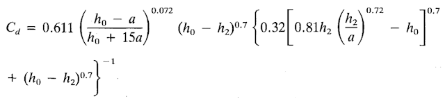
Discharge coefficient for Submerged Flow Condition

Under submerged flow conditions the discharge
coefficient is zero when ho = h2 (the tailwater
depth).
For submerged flow to exist, the following condition
is to be satisfied:

On the other hand, the condition for existence of free flow is:

Resultant Force on The Gate


γ= specific weight
of water = ρg
ρ = density
of water
Q = flow rate
v1, d1 = upstream velocity and depth
v2, d2 = downstream velocity and depth
w = width of rectangular channel /
flow width

Example:
A sluice gate is used to control the water flow rate over a dam. The gate is 20 ft wide, and the depth of the water above the bottom of the sluice gate is 16 ft. The depth of the water upstream of the gate is 20 ft, and the depth downstream is 3 ft. Estimate the flow rate under the gate and the force on the gate. The water density is 62.4 lb./ft3.

Solution:
V2 = 33.5 ft/s
V1 = 5.02 ft/s
Q = 2010 ft3/s
Fg = 1.33 x 10⁵
lb.
Swamee, P. K. (1992). SLUICE-GATE
DISCHARGE EQUATIONS. In Journal of Irrigation and Drainage Engineering
(Vols. 118, Issue 1, pp. 56–59). ASCE. http://pubs.asce.org/copy