

Geometrical Constructions and Conic Sections
BISECT A LINE AND AN ARC
1.
Bisect A 90 mm long line and A circular
arc AB.

·
Draw either a straight-line AB measuring 90
mm in length and an arc labeled AB.
·
Adjust the compass to a radius longer than
half the distance of AB. Using point, A as the center, draw arcs above and
below AB.
·
Without changing the compass radius, place
the compass at point B and draw arcs above and below AB that intersect the arcs
at points C and D.
·
Connect points C and D with a straight
line. This line is the perpendicular bisector that divides AB into two equal
parts.
PERPENDICULAR TO A LINE
2.
Draw a perpendicular line to an 80 mm long
straight-line AB, at a point P lying on the line at a distance of 30 mm from
the end A.
Method-I

1. Draw
a straight-line AB measuring 80 mm and locate a point P on it, positioned 30 mm
from point A.
2. Using
a compass set to any suitable radius, place the compass at point P and draw an
arc that intersects line AB at two points, C and D.
3. Adjust
the compass to a radius greater than half the distance between C and D. With
the compass centered at points C and D, draw two arcs that cross each other at
point E.
4. Connect
point P to point E using a straight line. The resulting line PE will be
perpendicular to line AB.
Method-II

1. Draw
a straight-line AB, 80 mm in length, and mark a point P on it such that P is 30
mm from point A.
2. Select
a point O at any location outside the line AB. Using O as the center, draw a
circle with a radius equal to the distance OP, ensuring it intersects the line
AB at point C.
3. Connect
point C to O and extend the line to meet the circle again at point D.
4. Join
point P to D. The line PD will be perpendicular to the line AB.
3.
Draw a perpendicular to an 80 mm long line AB,
from a point P lying at a distance 50 mm from end A and 60 mm from end B.
Construction
a. Draw an 80 mm long line AB.
b. With centre A and radius 50 mm draw an arc.
c.
With centre B and radius
60 mm draw another arc to intersect previous drawn arc at point P.

Method 1
1. Set the compass to any convenient radius and
with centre P, draw an arc CD to meet the line AB at points C and D.
2. Reset the compass to a radius greater than half
of CD and centres C and D respectively, draw arcs to intersect at point E.
3. Join P to E. Line PE is perpendicular to AB.
PARALLEL LINES
4.
Draw a line parallel to a given straight-line AB
through a point 50 mm away from it.

1.
Mark any point D on the line AB. With
centre D and radius DC, draw arc CE to meet AB at point E.
2.
With centre E and the same radius DC, draw
an arc DF.
3.
With centre D and radius of chord length CE,
draw an arc to intersect arc DF at point F.
4.
Join C to F. Line CF is parallel to the
line AB.
DIVIDE A LINE
5.
Divide an 80 mm long straight line into seven
equal parts.

a. Draw
an 80 mm long straight-line AB.
b. Draw
another line AC at any convenient acute angle with AB.
c. Set
the divider to a convenient length and mark off seven equal spaces on AC. Let
these points be 1’, 2’, 3’, 4’, 5’, 6’, and 7’.
d. Join
7’ to B.
e. Set
the drafter along 7’ B and draw parallel lines through points 1’, 2’, 3’, 4’, 5’,
6’ to meet AB at points 1, 2, 3, 4, 5 and 6 respectively.
f. These
points divide AB in seven equal parts.
ANGLE BISECTOR
6.
Draw an angle of 75° and bisect it with the help
of a compass.

1. Draw
an angle AOB which is equal to 75°.
2. Set
compass to any convenient radius and with centre O, draw an arc CD to meet
lines OA and OB at points C and D respectively.
3. Reset
the compass to any radius greater than half of chord length CD. With centres C
and D respectively, draw arcs to intersect each other at point P.
4. Join
O to P. Line OP is the bisector of the angle AOB.
CENTRE OF AN ARC OR CIRCLE
7.
Locate the centre of the arc shown in Fig.

1. Draw two chords CD and EF of any convenient
lengths in the arc.
2. Draw
PQ as the bisector of chord CD.
3. Similarly,
draw RS as the bisector of chord EF.
4. Let
the lines PQ and RS, produce if required, to intersect each other at point O.
The point O is the required centre of the arc.
5. This
method can also be used to determine the centre of a circle.
CIRCLE THROUGH THREE POINTS
8.
Draw a circle passing through three points A, B
and C not lying in a straight line.

1.
Mark points A, B and C. Join AB and BC.
2.
Draw PQ as the perpendicular bisector of
line AB. Similarly, draw RS as the perpendicular bisector of line BC.
3.
Let the lines PQ and RS, produced if
required, to intersect each other at point O. This point O is the required
centre of the circle.
4.
Draw a circle with centre O and radius OA
(= OB =OC). This circle passes through points A, B and C.
DIVIDE A CIRCLE
9.
Divide
a 50 mm diameter circle into 12 equal segments.

a. Draw a circle with centre O and 50 mm diameter.
b. Using drafter, draw diameters AG and DJ,
perpendicular of each other.
c. Draw arcs of radius equal to the radius of the
circle (= 25 mm) and centre A to meet the circumference of the circles at
points C and K.
d. Similarly, draw arcs of the same radius (= 25
mm) and centres D, G and J respectively, to meet the circumference of the
circle at points B, F, E, I, H and L. The points divide the circumference of
the circle into 12 equal segments.
TANGENT TO TWO
CIRCLES
10.Draw exterior and interior tangents connecting two circles
of radii 25 mm and 40 mm having their centres 100 mm apart.

Tangent BC common to two
circles (a) Exterior (b) Interior
a. Draw a 100 mm long line O1O2.
b. Draw a circle with centre O1 and radius R1 (= 25
mm).
c. Draw another circle with centre O2 and radius R2
(= 40 mm).
Exterior Tangent
a. Draw an arc with centre O2 and radius R2 – R1 (=
15 mm).
b. Through point O1, draw a tangent to this arc to
touch at point A.
c. Join O2A and produce it to meet the circle at
point B.
d. Through B, draw a line BC parallel to O1A, to
touch the smaller circle at point C. Line BC is the required tangent exterior
to the circles.
Interior Tangent
a. Draw an arc with centre O2 and radius R2 + R1 (=
65 mm).
b. Through point O1, draw a tangent to this arc to
touch at point A.
c. Join O2 to A which intersect the bigger circle
at point B.
d. Through B, draw a line BC parallel to O1A, to
touch the smaller circle at point C. Line BC is the required tangent interior
to the circles.
CIRCLE TO CONNECT
ANOTHER CIRCLE AND A POINT
11.Draw a circle of 60 mm diameter and mark a point P 70 mm
away from its centre. Draw another circle which passes through the point P and
is tangential to that circle at point Q.

a. Draw a circle of diameter 60 mm with centre O.
Mark a point Q on the circle.
b. Mark point P at a distance 70 mm from O.
c. Join PQ. Draw line AB as the bisector of line
PQ.
d. Let the line AB, produced if required, intersect
the line OQ produced at point C. Draw a circle with centre C and radius CQ (=
CP). This is the required circle.
Polygons
- A polygon is a closed curve made of a set of
line segments connected end to end, with no two segments crossing.
- The straight-line segments are called sides (or
edges).
- The points where sides meet are called vertices.
- Types of polygons by sides:
- 3 sides → Triangle
- 4 sides → Quadrilateral
- 5 sides → Pentagon
- Convex polygon:
Any two points inside can be joined by a line segment that does not
intersect any side.
- Concave polygon:
If a line joining two interior points intersects a side.
- Equilateral polygon:
All sides are equal in length.
- Equiangular polygon:
All interior angles are equal.
- Regular polygon:
Both equilateral and equiangular (e.g., equilateral triangle, square).
- Applications:
Construction of regular polygons is common in engineering drawings (e.g.,
nut-bolt assemblies, spanners, gears, etc.).


CONSTRUCTION OF
REGULAR POLYGONS
12.Draw a regular pentagon and a regular heptagon of 40 mm
sides, using general method.

General method 1 for (a)
pentagon (b) heptagon
Method 1 (a) for pentagon and
(b) for heptagon.
1. Draw a 40 mm long line OA.
2. Draw a semicircle AP with centre O and radius
OA.
3. Divide the semi-circular AP into n equal parts,
where n is the number of sides of the polygon (n = 5 for pentagon and n = 7 for
heptagon). Starting from point P, mark these divisions as 1, 2, 3, 4, etc.
4. Join O2, O3, O4, etc.
5. Draw an arc with centre 2 and radius OA to cut
the line O3 produced at B.
6. Draw another arc with centre B and the same
radius OA to cut line O4 produced at C. For heptagon, proceed to draw arcs with
centres C and D, radius OA to meet lines O5 and O6 produced at points D and E,
respectively.
7. Join the points O, 2, B, C, …, A and obtain the
required polygon.

General method 2 for (a)
pentagon (b) heptagon
Method 2: Refer to
Fig. (a) for pentagon and Fig. (b) for
heptagon.
1. Draw a 40 mm long line AB.
2. Draw PQ as perpendicular bisector to AB (Problem
3.1).
3. Describe a semicircle with diameter AB, to
intersect PQ at 4.
4. With either A or B as the centre, draw an arc of
radius AB to meet PQ at 6.
5. Bisect the line 4-6 and obtain point 5 on PQ.
6. Mark points 7 and 8 on PQ such that the lengths
4–5, 5–6, 6–7, 7–8 are equal.
7. Draw a circle with centre 5 for pentagon and 7
for heptagon, to pass through points A and B.
8. Taking AB as radius cut the circle at C, D, E,
etc., and join them to get the required polygon.
CONSTRUCTION OF A
REGULAR HEXAGON
13.Draw a regular hexagon of 40 mm sides, keeping a side (a)
vertical (b) horizontal

Hexagon with a side (a)
Vertical (b) Horizontal
a. Draw a circle with centre O and radius 40 mm.
b. Mark a diameter AD in vertical position for case
(a) and in horizontal position for case (b).
c. With radius OA and centres A and D, draw arcs to
cut the circle at points B, F, C and E.
d. Join ABCDEF to get the required hexagon.
CONE
A cone is a
three-dimensional geometric shape with a circular base that tapers smoothly to
a single point called the apex or vertex.
A cone is formed if a right-angled
triangle with an apex angle α is rotated about its altitude as the axis. The
apex angle of the cone is 2α.

ELLIPSE
When a cone is cut by a
plane inclined to its axis in such a way that it intersects all the generators,
the resulting section is an ellipse. For the section to form an ellipse, the
cutting plane's inclination must exceed half of the cone's apex angle. θ >
α.

Applications:
·
Concrete arches
·
Dams
·
Monuments structure, etc.
PARABOLA
When a cone is cut by a
plane inclined to its axis and parallel to one of its generators, the resulting
section is a parabola. In this case, the cutting plane's inclination is equal
to half of the cone's apex angle. θ = α.

Applications:
·
Bridges
·
Antenna etc.
HYPERBOLA
When a double cone is
sliced by a plane that goes through both halves, the section formed is a
hyperbola. This happens when the cutting plane does not intersect the apex and
is inclined at an angle less than half of the cone's apex angle. θ < α


Applications:
·
Water channel
·
Cooling Tower
·
Radio Astronomy
·
Telescope reflectors etc.
CONSTRUCTION OF
ELLIPSE
An ellipse can be construction by the following
methods:
1. Eccentricity method (general method)
2. Intersecting arcs method or arcs of circles
method
3. Concentric circles method
4. Oblong method
a. Rectangle method
b. Parallelogram method
ECCENTRICITY METHOD
An ellipse is defined as
the locus of a point P moving in a plane in such a way that the ratio of its
distance from a fixed point F1 to the fixed straight-line DD’ is a constant and
is always less than unity.


14.Draw an ellipse when the
distance of its focus from its directrix is 50 mm and eccentricity is 2/3.
Also, draw a tangent and a normal to the ellipse at a point 70 mm away from the
directrix.
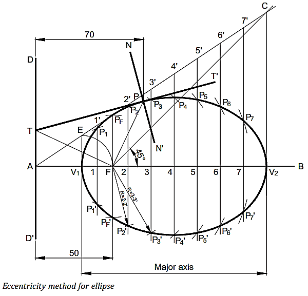
Construction
1. Draw a vertical line DD’ to represent directrix.
2. Draw the principal axis AB perpendicular to DD’.
3. Mark focus F on the axis AB such that AF = 50
mm.
4. Divide AF into five equal divisions. Mark the
vertex V1 on the third division point from A. Therefore, V1F/V1A = 2/3 and
thereby the vertex V1 represents a locus point of the ellipse.
5. Draw a vertical line V1E equal to V1F. Join A to
E and produce it to some distance. Therefore, in the triangle AV1E, V1E/V1A =
V1F/V1A = 2/3
6. Draw a line from the focus F, inclined at 45° to
the axis AB to intersect the line AE produced at point C. Draw a perpendicular
line from point C to meet the axis AB at point V2. The line V1V2 represents the
major axis of the ellipse.
7. 7. Mark a point 1 anywhere on the major axis V1V2.
Draw a line through point 1, perpendicular to the axis AB to meet line AE produced
at point 1’. Therefore, 11’/1A = V1E/V1A = 2/3.
8. With centre F and radius equal to 1-1’, draw
arcs to intersect the perpendicular line 1-1’ at points P1 and P1’. These are
the loci points of the ellipse because FP1/1A = FP1’/1A = 11’/1A = 2/3.
9. Similarly, mark some more points, say 2, 3, 4,
etc., on the major axis V1V2 which need not be equidistant and repeat steps 7
and 8. This will give some more loci points of the ellipse like; P2 and P2’, P3
and P3’, P4 and P4’, etc.
10. Join all
the loci points of the ellipse and obtain the required ellipse.
Tangent and normal
to an ellipse
1. Mark a point P on the ellipse at a distance of
70 mm from the directrix and Join PF.
2. Draw a line FT perpendicular to the line PF to
meet the directrix DD’ at point T.
3. Join TP and produce to some point T’. The line TT’
is the required tangent.
4. Through point P, draw a line NN’ perpendicular
to TT’. The line NN’ is the required normal.
CONSTRUCTION OF
PARABOLA
A parabola can be constructed by the following
methods:
1. Eccentricity method
2. Offset method
3. Tangent method
4. Oblong method
a. Rectangle method
b. Parallelogram method
ECCENTRICITY METHOD
A parabola is defined as
the locus of a point P moving in a plane in such a way that the ratio of its
distance from a fixed point F to the fixed straight line DD’ is a constant and
is always equal to unity.


15.Draw a parabola when the
distance between its focus and directrix is 50 mm. Also, draw a tangent and a
normal at a point 70 mm from the directrix
Construction

1. Draw a vertical line DD’ to represent the
directrix.
2. Draw the principal axis AB perpendicular to the
directrix DD’.
3. Mark focus F on the axis AB such that AF = 50
mm.
4. Mark vertex V at the mid of AF. This vertex V is
the locus point of the parabola because e = VF/AV = 1
5. Mark a point 1 anywhere on the axis AB and draw
a perpendicular line through it.
6. With centre F and radius equal to A1, draw arcs
to intersect the perpendicular line through point 1 at points P1 and P1’. These
are the loci points of the parabola because FP1/A1 = FP1’/A1 = 1
7. Similarly, mark some more points, say 2, 3,
etc., on the axis AB which need not be at equidistant and repeat Step 6. This
will give some more loci points of the parabola like; P2 and P2’, P3 and P3’
etc.
8. Join all the loci points P2’, P1’, V, P1, P2,
etc., by a smooth curve and obtain the required parabola.
Tangent and normal
to a parabola
1. Mark a point P on the parabola at a distance of
70 mm from the directrix and join PF.
2. Draw a line FT perpendicular to the line PF to
meet the directrix DD’ at point T.
3. Join T to P and produce to some point T’. The
line TT’ is the required tangent.
4. Through point P, draw a line NN’ perpendicular
to TT’. The line NN’ is the required normal.
CONSTRUCTION OF
HYPERBOLA
A hyperbola can be constructed by the following
methods:
1. Eccentricity method
2. Intersecting arcs method
3. Oblong method
4. Intercept method
5. Asymptotes method
(a) Orthogonal asymptotes method
(b) Oblique asymptotes method
ECCENTRICITY METHOD
A hyperbola is defined
as the locus of a point P moving in a plane in such a way that the ratio of its
distance from a fixed point F to the fixed straight line DD’ is a constant and
is always greater than unity.


16.Draw a hyperbola when the
distance of its focus from its directrix is 50 mm and eccentricity is 3/2.
Also, draw a tangent and a normal to the hyperbola at a point 25 mm from the
directrix.

Construction
1. Draw a directrix DD’.
2. Draw the principal axis AB
perpendicular to the directrix DD’.
3. Mark focus F on the axis
AB such that AF = 50 mm.
4. Divide AF into five
equal divisions. Mark the vertex V on the second division-point from A.
Therefore, VF/VA = 3/2 and thereby the vertex V represents a locus point of the
hyperbola.
5. Draw a vertical line VE equal
to VF. Join A to E and produce it to some distance. Therefore, in the triangle AVE,
VE/VA = VF/VA = 3/2.
6. Mark a point 1 anywhere
on the axis AB. Draw a line through point 1, perpendicular to the axis AB to
meet line AE produced at point 1’. Therefore, 11’/1A = VE/VA = 3/2.
7. With centre F and radius
equal to 1-1’, draw arcs to intersect the perpendicular line 1-1’ at points P1 and
P1’. These are the loci points of the hyperbola because FP1/1A = FP1’/1A = 11’/1A
= 3/2.
8. Similarly, mark some
more points, say 2, 3, 4, etc., on the axis AB which need not be equal and repeat
Steps 6 and 7. This will give some more loci points of the ellipse like; P2 and
P2’, P3 and P3’, P4 and P4’, etc.
9. Join points P4’, P3’, P2’,
P1’, V, P1, P2, P3, P4 by a smooth curve. This is the required hyperbola.
Tangent and normal
to a hyperbola
1. Mark a point P on the
hyperbola at a given distance, 25 mm from the directrix. Join PF.
2. Draw a line FT perpendicular
to PF to meet the directrix at point T.
3. Join TP and extend it to
some point T’. The line TT’ is the required tangent.
4. Through point P, draw a line NN’ perpendicular
to TT’. The line NN’ is the required normal.